 Main Number
 Find us on
 Reach us @
What determines whether cement reaches the mixer reliably: the silo, the conveying line, or the way the entire system is engineered together? For Australian projects, dependable Concrete Batching Plants rely on storage, pneumatic transfer and batching equipment working as one coordinated arrangement, designed around site layout and material-handling requirements.
With quality German engineering and hundreds of installations all over the world, GPE Group designs batching plants and cement terminal systems around each project’s practical requirements. Its Concrete Batching Plants have been used to manufacture world landmarks, including Burj Khalifa, where the highest quality of concrete was used. This article follows the cement path from storage to batching, explains how to assess transfer options and system interfaces, and outlines the project information that supports effective integration. It also covers turnkey delivery from design through commissioning, with after-sales service and spare parts provided around the world.
Key Takeaways
- Map the cement path from silo storage through transfer to the batching operation, and identify the interface between each stage.
- Define required output, storage needs, site layout, transfer route and batching interface before settling on a system arrangement.
- Assess possible interruption points by reviewing material flow, connections between equipment and access for inspection and service planning.
- For Concrete Batching Plants, bring raw-material availability, budget and local standards into the design discussion alongside production requirements.
- Understand how turnkey delivery can coordinate design, manufacturing, testing, supply, transport, erection and commissioning within one project scope.
What Is a Cement Silo Pneumatic Conveying System?
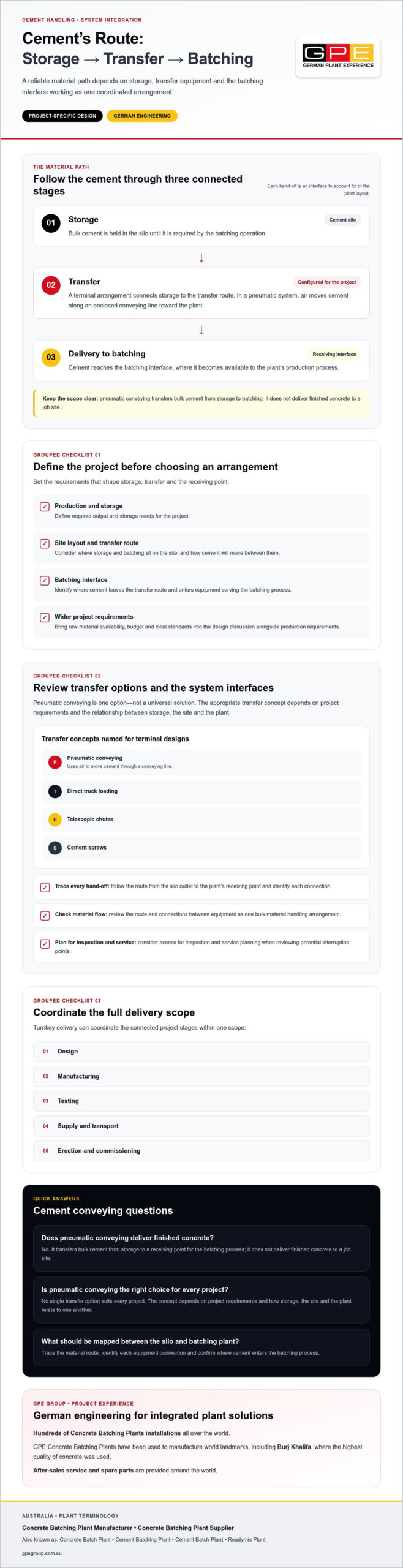
A cement silo pneumatic conveying system transfers bulk cement from storage to a batching process by moving it through a conveying line using air. It connects the silo with the batching operation. It does not deliver finished concrete to a job site.
That distinction helps when defining the scope of a project. The silo stores cement, the conveying arrangement transfers it, and the batching plant receives and proportions it as part of concrete production. These functions are separate, but their interfaces need to be designed together. Start by identifying where cement will be stored, how it will move across the site and where it will enter the batching process.
How Pneumatic Conveying Fits into Cement Handling
The material path starts at storage and continues through a transfer route to a receiving point associated with batching. A conveying line is the enclosed route through which air moves cement between these points. The discharge point is where cement leaves the route and enters equipment serving the batching process.
Plan these elements as one bulk-material handling arrangement, rather than treating pneumatic conveying as an isolated silo feature. The position of the storage, the site layout and the plant’s receiving interface all shape the transfer route. For general context on the wider plant and its components, see this overview of a concrete batching plant.
Pneumatic Conveying and Other Cement Transfer Arrangements
Pneumatic conveying is one method of moving cement through a line using air. In a cement-storage system, it connects stored material with the batching process as part of a wider transfer design.
A cement silo pneumatic conveying system uses air to transfer bulk cement from storage through a conveying line to the receiving point for batching.
Pneumatic conveying is one option in a cement terminal arrangement, not a universal solution for every project. GPE terminal designs can incorporate pneumatic conveying, direct truck loading, telescopic chutes or cement screws. The appropriate transfer concept depends on the project requirements and the relationship between storage, the site and the plant.
For Concrete Batching Plants, this system-level view clarifies how silo storage, transfer arrangements and batching equipment connect. GPE applies German engineering to project-specific plant and terminal designs, coordinating these functions around the required site layout and material-handling needs.
How Cement Moves from Storage through a Pneumatic Conveying System
Understanding the movement sequence makes it easier to assess how storage, transfer and batching interfaces fit together. The arrangement depends on project requirements and site conditions, so an identical conveying configuration should not be assumed for every plant.
From Cement Storage to the Transfer System
A cement silo provides the storage point. The project design connects it to the transfer arrangement, taking into account the positions of the silo and the batching operation. A cement terminal can bring storage and transfer together in a configuration shaped around project needs.
Use this three-stage sequence to map the material path:
- 1. Storage: Bulk cement is held in the silo until it is required by the batching operation.
- 2. Transfer: The terminal arrangement connects storage to a conveying route. In a pneumatic system, air moves cement along the conveying line towards the plant.
- 3. Delivery to batching: Cement reaches the receiving point or batching interface, where it becomes available to the plant’s production process.
Each transition is an interface, where one function hands material to the next. When reviewing a proposed layout, trace the route from the silo outlet to the plant’s receiving point and identify each connection. This helps the design account for the site layout and the relationship between storage and batching without assuming a particular route, distance or operating rate.
From Conveying to the Batching Plant
At the endpoint, the conveying arrangement must meet the batching operation’s receiving interface. The specific equipment layout depends on the plant design. The key planning task is to align the cement terminal’s transfer arrangement with the batching process it serves. For a broader explanation of plant operation, see How Does a Concrete Batching Plant Work: System Mechanics.
Process summary: Cement is stored in a silo, transferred through an arrangement configured for the project, and delivered to the batching interface for use in production.
Coordinated design keeps these stages connected as one material-handling path. Cement transfer and cement quality are distinct considerations, and production also depends on appropriate quality controls. The US National Institute of Standards and Technology describes reference materials used in cement manufacturing and testing standards.
GPE designs cement terminal and batching plant solutions around the storage-to-batching arrangement. Explore cement terminal and batching plant solutions as part of an integrated project scope.
Which Design Factors Shape a Cement Silo Pneumatic Conveying System?
A dependable design starts with project requirements, not a generic equipment template. For Concrete Batching Plants, the storage and conveying arrangement needs to align with required output, available raw materials, site configuration, budget and local standards. GPE custom-tailors plant designs around these considerations, applying German engineering to the project scope.
Before selecting equipment, use this framework to establish the key interfaces:
| Design factor | What to establish | Why it matters |
|---|---|---|
| Project demand | Required material flow and intended production needs. | Provides a basis for aligning cement supply with the batching operation. |
| Storage arrangement | Required cement storage, silo location and relationship to the plant. | Shapes how storage connects with the transfer system and site layout. |
| Transfer route | How the conveying arrangement will connect storage to the plant. | Defines the path and interfaces the system must accommodate. |
| Batching interface | Where and how cement is received by the batching operation. | Ensures the terminal arrangement is considered alongside plant design. |
Project Requirements, Materials, and Site Constraints
Before developing the arrangement, establish material flow, storage needs, site layout and the intended batching interface. Raw-material availability and local standards also inform the plant design. If the wider project involves other bulk materials, define their handling requirements separately rather than assuming they use the same system configuration as cement.
These inputs are central to both Cement Terminal Plant Design & Bulk Handling Solutions and Industrial Cement Silos: Engineering, Sizing & Integration. For additional technical context on pneumatic system design, the Pneumatic Conveying Design Guide is a reference focused on conveying system design and operation.
Storage Capacity and Transfer Configuration
Storage capacity describes how much cement a silo can hold; it is not a measure of how much concrete a batching plant can produce. An individual silo in a cement terminal can have a capacity of up to 3,000 m³. A terminal handling up to 20,000 MT of cement may consist of several 3,000 m³ silos. These figures describe terminal storage, not batching output, and should not be treated as interchangeable.
GPE cement silos use bolted steel-panel construction. They are flat packed and transported in shipping containers, then bolted at site. Each unit is supplied with a special gasket that waterproofs the silo. These construction and transport details form part of the storage solution, while the terminal’s capacity remains distinct from the batching plant’s production output.
Storage capacity measures the cement held in a silo, while batching production capacity describes the plant’s concrete output. Keeping this distinction clear helps project teams assess terminal storage and plant requirements as related but separate design decisions.
How to Assess Reliability and Operational Risks in Cement Conveying
Reliable cement transfer depends on more than the conveying equipment alone. Storage, material flow, transfer route and the batching interface must be considered as a coordinated system, with components arranged to suit the site and intended operation. For Concrete Batching Plants, this integrated approach helps project teams identify potential interruption points during design rather than assessing each item of equipment in isolation.
Blockages and interruptions are operational risks to assess, not outcomes that can be ruled out by a general claim. The appropriate design response depends on project conditions, including material characteristics, the transfer arrangement and how cement is received at the plant. Review each connection and consider whether components can be accessed for inspection and service planning. Detailed engineering decisions must be made for the particular installation; general guidance cannot replace site-specific design or safe operating procedures.
Common Conveying-System Questions to Resolve at Design Stage
At design stage, establish how the selected cement will move from storage to the batching operation and how each transition will be managed. Material characteristics inform the conveying arrangement, while the site layout shapes the route and the plant defines the receiving point. Review these elements together, because a change at one interface may affect the wider material path.
- Material: Which characteristics of the cement need to inform its movement through the proposed arrangement?
- Route: How will the conveying system connect the silo outlet with the plant?
- Interfaces: How will material pass from storage into conveying and from the conveying route into batching?
- Access: How are system components arranged for inspection and service planning?
These questions help define the assessment; they do not prescribe universal specifications. Site-specific engineering determines the appropriate configuration and how potential blockage points or interruptions should be addressed.
Service, Spare Parts, and Continuity
Operational readiness also includes planning for support across the plant’s working life. Consider service requirements and spare-parts access alongside the system design, so these needs are part of lifecycle planning rather than an afterthought. This planning does not establish a particular response time, stock level or maintenance outcome.
GPE provides after-sales service and spare parts around the world. With offices in Germany, Italy, Dubai and Australia, and installations all over the world, GPE combines quality German engineering and project-specific design with support for plant operations.
For an integrated approach to cement storage and conveying, explore GPE’s plant and terminal solutions.
How GPE Integrates Cement Conveying with Concrete Batching Plants
For project teams, an integrated solution coordinates cement storage and transfer with the batching plant from the outset. As a Concrete Batching Plant Manufacturer and Concrete Batching Plant Supplier in Australia, GPE applies quality German engineering to project-specific plant and terminal designs, incorporating pneumatic conveying where it suits the required bulk-handling arrangement.
Project-Specific Integration from Design to Commissioning
GPE tailors plant designs around required output, raw-material availability, budget and local standards. These considerations inform how the batching plant and cement-handling system are planned together, with the terminal configuration shaped by project requirements and site conditions.
GPE’s turnkey scope covers design, manufacturing, testing, supply, transport, erection and commissioning. This coordinated delivery connects storage, the transfer route and the batching interface within the project scope. Pneumatic conveying is one possible element of a cement terminal and bulk-handling arrangement, selected to suit the installation rather than applied as a universal configuration.
GPE has completed hundreds of Concrete Batching Plant installations all over the world. Its offices are in Germany, Italy, Dubai and Australia, and GPE installs all over the world. GPE Concrete Batching Plants have been used to manufacture world landmarks, including Burj Khalifa, where the highest quality of concrete was used.
Worldwide Support for Batching Plant Operations
Planning extends beyond commissioning. For concrete producers and infrastructure project teams, considering after-sales support and spare-parts access alongside plant integration helps account for lifecycle requirements. GPE provides after-sales service and spare parts around the world, with offices in Germany, Italy, Dubai and Australia and installations all over the world.
By aligning plant design, cement terminal arrangements and project delivery, GPE brings German engineering to integrated batching solutions for Australian requirements. Project stakeholders can discuss concrete batching plant and cement handling requirements with GPE.
Plan Your Integrated Batching System with Confidence
Reliable cement handling comes from designing storage, conveying and batching as connected functions, then tailoring the arrangement to project requirements and site conditions. Keeping silo storage capacity distinct from batching output also helps teams define the project scope and assess each part of the system accurately.
GPE brings quality German engineering and international project experience to Concrete Batching Plants, with hundreds of installations completed all over the world. GPE plants have been used to manufacture world landmarks, including Burj Khalifa, where the highest quality of concrete was used. GPE provides after-sales service and spare parts around the world, with offices in Germany, Italy, Dubai and Australia and installations all over the world.
For Australian producers and infrastructure teams, a clear understanding of required output, raw-material availability, site layout and local standards gives the design process a practical foundation. An integrated project scope can then connect cement storage and transfer with the batching plant, from design through commissioning.
Discuss your concrete batching plant and cement handling requirements with GPE to start planning a solution shaped around your project.
Frequently Asked Questions
How does a cement silo pneumatic conveying system work?
A cement silo pneumatic conveying system transfers bulk cement from storage towards a receiving point through a designed conveying arrangement. In a batching application, it links silo storage with the plant’s cement-handling interface. The layout depends on the project’s materials, site configuration and operational requirements, so do not assume one arrangement will suit every installation. Transfer distances, pressures and operating rates require project-specific engineering.
Can pneumatic conveying connect a cement terminal directly to a concrete batching plant?
Yes. A cement terminal can be designed with pneumatic conveying and transfer arrangements serving a batching operation. The connection is engineered around the terminal, site layout, transfer route and receiving interface at the plant. GPE tailors terminal systems to project requirements, so the configuration is based on the installation. The key planning principle is to coordinate storage, transfer and batching rather than assume one standard layout suits every site.
What information is needed to design a cement conveying system?
Design planning should establish material-handling requirements, the storage arrangement, site layout, intended plant interface and relevant project constraints. GPE custom-tailors plant designs around required output, raw-material availability, budget and local standards. These inputs help define how the terminal and batching plant should connect. Universal minimum capacities, conveying distances or operating pressures should not be assumed, because appropriate specifications depend on the project and its engineering design.
How much cement can a GPE cement terminal store?
An individual silo in a GPE cement terminal can hold up to 3,000 m³. A terminal handling up to 20,000 MT of cement may consist of several 3,000 m³ silos. These figures refer to terminal storage capacity, not the concrete production capacity of a batching plant. Keep storage volume and production output distinct when defining a project’s material supply and batching requirements.
Can a pneumatic conveying system handle materials other than cement?
GPE’s bulk-handling systems cover materials including cement, fly ash, ground slag, quick lime, minerals and ores. The intended material informs the system design, because one conveying configuration or operating specification should not be assumed to suit every product. Project-specific material-handling requirements guide the arrangement of storage and transfer equipment.
Are GPE Concrete Batching Plants designed in line with Australian Standards?
GPE tailors plant designs around local standards, alongside required output, raw-material availability, budget and site requirements. The specific standards relevant to a project should be identified as part of its design requirements. This provides a practical basis for developing a plant design that accounts for applicable local standards without assuming a particular standard or certification.
Does GPE provide spare parts and after-sales service internationally?
Yes. GPE provides after-sales service and spare parts around the world. Its offices are in Germany, Italy, Dubai and Australia, and it installs all over the world. Support planning can be considered alongside the plant’s design and lifecycle requirements. This does not imply a particular response time, spare-parts inventory level or uptime outcome.