 Main Number
 Find us on
 Reach us @
A cement terminal is only as dependable as the route that moves material through it. Storage capacity is important, but a cement terminal storage and transfer system must also coordinate receipt, conveying, silo storage and dispatch. Each interface affects how the system fits the site and how cement moves through the facility.
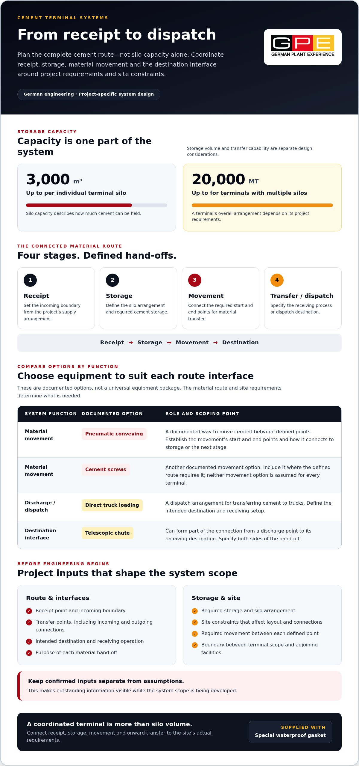
For project teams defining a terminal in Australia, the challenge is not simply selecting silo volume. It is matching transfer options to each point in the material route and identifying the site and operating requirements that shape the complete scope. GPE Group designs cement terminal systems around project requirements and site constraints. An individual terminal silo can provide up to 3,000 m³ capacity, while multiple silos can form terminals handling up to 20,000 MT of cement.
This reference explains the main system stages and the roles of pneumatic conveying, cement screws, telescopic chutes and direct truck loading. It also sets out the project information to assemble before engineering, including the required material route, storage arrangement, transfer points and site constraints. Considered together, these inputs help turn a capacity requirement into a coordinated handling solution. Every unit is supplied with a special waterproof gasket.
Key Takeaways
- Plan the terminal as a connected material route, not as silo capacity alone.
- Match pneumatic conveying and cement screws to movement needs, and direct truck loading or telescopic chutes to the destination interface.
- Define the receipt point, storage requirement, transfer points, destination and site constraints before engineering begins.
- Separate confirmed project inputs from assumptions so outstanding information is clear when developing the system scope.
What a Cement Terminal Storage and Transfer System Does
A cement terminal storage and transfer system connects bulk cement storage with the process or destination that receives the material. Its operating boundary extends beyond the silo: it includes the route by which cement arrives, where it is stored, and how it is moved or dispatched. This connected approach reflects the principles of Bulk Material Handling, where equipment and material flow are considered together.
The exact endpoints depend on the project. Cement may arrive through a project-defined supply arrangement, move into storage, then transfer to another process or a dispatch point. Describe the terminal as a route before deciding which equipment is needed. That makes it easier to establish what the system must receive, hold and deliver, without assuming a receipt method or transfer configuration that may not suit the site.
The Material Route Through a Cement Terminal
Receipt, storage, movement and dispatch are connected stages. At each hand-off, material passes from one part of the operation to another. The terminal scope needs to account for these interfaces, including the receipt boundary set by the project’s supply arrangement and the destination boundary set by how cement will be used or dispatched.
Material route: Receipt → Storage → Movement → Transfer or dispatch to intended destination
This sequence is functional rather than equipment-specific. It shows where the terminal begins and ends without presuming a receipt method or assigning machinery before the site requirements are understood. For each transition, identify the incoming and outgoing points, the purpose of the hand-off, and the connection that the design must accommodate.
Mapping the whole route also helps separate the terminal’s scope from adjoining facilities. For example, defining the receipt point and destination clarifies which connections belong within the terminal arrangement and which link to other project systems. This is useful when several project teams are responsible for connected parts of a facility.
Storage Capacity Versus Transfer Capability
Storage capacity describes how much cement the terminal can hold. Transfer capability describes the functions needed to move cement into, through and out of that storage arrangement. These are related but separate design considerations: a silo volume does not by itself specify how material reaches the silo or how it leaves for its intended destination.
Discharge arrangements and destination interfaces influence the equipment scope because storage must connect to the next point in the route. That point might be another process or a dispatch interface, depending on project requirements. Defining it early prevents a capacity figure from being mistaken for a complete operational specification.
Terminal performance depends on coordinated system interfaces, not storage volume alone.
Assess the terminal as an integrated sequence: receipt, storage, movement and onward transfer. Establishing those boundaries gives the engineering process a practical basis for identifying required functions, site constraints and connections to adjacent operations.
The Main Components of a Cement Terminal Storage and Transfer System
Understand each component by the function it performs along the material route. The silo provides storage; conveying connects defined points; discharge releases cement from storage; and the destination interface connects terminal equipment with the receiving operation. Together, these functions make up the handling arrangement. The project route determines which documented options are needed.
The material handled at a terminal is the finished product of a wider manufacturing process. The Portland Cement Association: Cement Manufacturing Process provides context on cement production. Terminal engineering focuses on the storage and transfer stages required at the site.
Storage and Material Movement
The silo holds cement until it is needed for the next movement or dispatch. Its role is distinct from the equipment that brings material to storage or transfers it onwards. Every unit is supplied with a special waterproof gasket. The overall layout and connections depend on the defined material route and the constraints of the site.
Pneumatic conveying and cement screws are documented options for moving material. To define their role, establish the start and end points of each movement, then identify how the connection relates to storage or the next stage. Neither option is a universal requirement for every terminal. Their inclusion depends on the material route the project needs to support.
Discharge and Destination Interfaces
Direct truck loading and telescopic chutes are documented options at the discharge end. Direct truck loading describes a dispatch arrangement in which cement is transferred to trucks. A telescopic chute can form part of the connection between a discharge point and its receiving destination. Define the receiving setup before settling the interface; neither option should be assumed for every terminal.
An interface is the point where one system stage hands material to another. Define both sides of that hand-off: the terminal function delivering cement and the destination operation receiving it. This makes the equipment boundary clear and gives each selected component a specific role in the material route.
Functional system flow: Receipt → Silo storage → Pneumatic conveying or cement screws, where required → Discharge → Direct truck loading or telescopic chute, where suited to the destination
This flow is illustrative, not a fixed equipment sequence. Project requirements determine which movement and discharge options suit the route. GPE engineers cement terminal systems to accommodate project requirements and site constraints. Silos can be erected by local crews, and factory-trained engineers are always available for supervision. For projects defining storage and terminal functions, GPE cement terminal systems provide a basis for developing the arrangement.
Comparing Cement Terminal Transfer Options by Function
Compare transfer options by the part of the route they serve, rather than assuming one method is preferable for every application. In a cement terminal storage and transfer system, pneumatic conveying and cement screws are movement options. Direct truck loading and telescopic chutes relate to discharge or the destination interface. These functions are distinct, and the project layout determines which are required.
The table compares each option’s role in the route. It does not mean all four must be installed together, or that a particular option provides a specific capacity, speed or efficiency.
| Option | System role | Interface served |
|---|---|---|
| Pneumatic conveying | Moves cement between defined points in the terminal route. | The connection between the material’s origin point and its receiving point. |
| Cement screws | Provides a mechanical movement option between defined points. | The connection from a storage or transfer stage to the next stage. |
| Direct truck loading | Provides a dispatch option where cement is transferred directly to trucks. | The terminal-to-vehicle loading point. |
| Telescopic chutes | Provides an option at the point where cement is discharged to a destination. | The discharge connection with the receiving destination. |
Pneumatic Conveying and Cement Screws
Pneumatic conveying and cement screws can be incorporated as movement options in a project-specific terminal design. Compare them by where they fit in the defined route: which point supplies the material, where it needs to arrive, and how the connection relates to storage and discharge. This clarifies the functional scope without making unsupported claims about operating limits or relative performance.
For either option, specify the movement path and connection points in the project brief. Identifying the origin, receiving point and adjoining system stages helps establish where transfer equipment is needed and how it connects with the terminal arrangement. Include known site constraints when mapping that layout.
Truck Loading and Telescopic Chutes
At the dispatch end, direct truck loading means trucks are the receiving interface. Telescopic chutes are a separate documented option at a discharge interface, connecting the discharge point with its intended destination. Assess their roles against the receiving arrangement; they are not interchangeable and should not be treated as mandatory components.
Defining the destination first makes the comparison practical. Establish whether the route ends at truck loading, another receiving point or a configured discharge connection, then describe the interface the terminal must accommodate. GPE’s terminal arrangements are tailored to project requirements and site constraints. Selection therefore follows the route and destination, rather than a universal ranking of transfer options.
How to Define the Cement Terminal System Before Engineering
A useful design basis turns the project objective into clear material-handling requirements before equipment is selected. For a cement terminal storage and transfer system, record what the terminal must receive and deliver, the storage requirement, where transfers occur, and the site constraints that affect the layout. Separating confirmed information from assumptions helps the project team identify what is ready for engineering and what still needs definition.
Establish the Project Design Basis
Start with the material-handling objective and intended destination. Record the confirmed storage requirement and available site space, including known constraints that may affect the arrangement. Keep requested operating figures distinct from estimates. Unverified throughput, delivery frequency or operating patterns should not become fixed design inputs.
Use this sequence to organise the project information:
- Define the material route. Identify the planned receipt point, storage stage and intended destination without assuming a receipt method the project has not established.
- Record the storage requirement. State the required storage arrangement and distinguish confirmed capacity needs from preliminary estimates.
- Map transfer interfaces. Identify where material must move between stages and record the origin and receiving point for each required transfer.
- Document site constraints. Record known space limitations and relevant layout boundaries. Flag information still outstanding for engineering development.
Mark each input as confirmed, assumed or outstanding. A confirmed destination can guide interface definition; an assumed delivery pattern should remain an assumption, not an established operating requirement. This distinction gives the engineering work a reliable starting point while making further project-definition needs visible.
The system scope starts with the material route, storage arrangement, transfer method and destination interface.
Plan Interfaces, Transport and Site Assembly
Once the design basis is set out, locate the connection points between storage, transfer equipment and the destination. Relate each point to the site layout and intended discharge location. The aim is to make every connection and its role clear before settling an equipment configuration.
Include transport and site assembly in early project planning. Record access and space considerations relevant to delivering and assembling the selected arrangement, and flag unresolved site information. This allows installation planning to inform the engineering scope without treating assumptions as confirmed constraints.
For major infrastructure projects, consider terminal interfaces alongside the wider materials-production plan. The same discipline applies when selecting a concrete batching plant for an infrastructure project: define the operating objective and site requirements before finalising the equipment scope.
With the design basis organised, project teams can progress from requirements to a coordinated terminal arrangement. Discuss your cement terminal system requirements with GPE to develop an arrangement tailored to the project and its site constraints.
GPE Cement Terminal Systems: Storage, Transfer and Project Next Steps
Once the material route and interfaces are defined, consider storage capacity as part of the full project requirement. GPE engineers flexible cement terminal systems around project requirements and site constraints. This places storage within a coordinated terminal scope, rather than treating it as a standalone capacity decision. For Australian projects, the design basis should bring the intended site layout and required terminal scale together.
Documented GPE Terminal Configuration
An individual GPE terminal silo can provide up to 3,000 m³ capacity. Where project requirements call for a larger terminal, multiple silos can be assembled into terminals handling up to 20,000 MT of cement. These figures describe different scales: the capacity of an individual silo and the amount of cement handled by a multiple-silo terminal. The project’s storage requirement informs the appropriate arrangement.
Flexible terminal designs can address remote or space-constrained sites. The actual configuration must be developed around the site rather than assumed from a general example. Assess storage requirements, route interfaces and physical constraints together to define the terminal arrangement.
Modular Delivery, Erection and Next Steps
For transport and assembly, terminal units are flat packed and transported in shipping containers and bolted at site. This modular approach provides a basis for planning delivery and erection, while site conditions inform the assembly plan. A special waterproof gasket is supplied with every unit.
Local crews can erect silos, and factory-trained engineers are always available for supervision. Include the intended erection resources and supervision arrangements in project planning to connect the design with site installation. These provisions support coordinated planning without presuming a particular construction programme or site method.
As a next step, bring the required storage scale, material route, transfer interfaces and site constraints into one design basis. This gives the project team a complete view of the proposed terminal arrangement, whether the requirement is for an individual silo or a multiple-silo terminal.
Discuss your cement terminal project with GPE to develop a system arrangement aligned with your storage and site requirements.
Advance Your Terminal Project With a Clear Design Basis
As a project moves from concept toward engineering, a concise brief helps keep operating priorities and site planning aligned. Bring the relevant stakeholders around shared objectives, record decisions as they are made, and distinguish settled requirements from details still being developed. This gives the engineering team a clear starting point and maintains continuity as the scope evolves.
Early alignment is particularly useful when terminal interfaces connect with wider site operations. A structured brief gives the project team a practical reference for evaluating those connections and developing an arrangement suited to the facility. GPE applies German engineering to industrial plant design, with project requirements and site constraints informing the system arrangement.
Bring your project requirements into a focused discussion. Discuss your cement terminal project with GPE and move forward with a clearly defined basis for engineering.
Frequently Asked Questions
What does the special gasket supplied with a cement terminal do?
The special waterproof gasket supplied with every unit waterproofs the steel-panel joints. It addresses the silo structure, not the movement of cement through the terminal. Conveying and discharge equipment serve that separate material-handling function. Keeping these roles distinct helps clarify that the gasket is supplied as part of the silo, while transfer arrangements are defined by the route and its interfaces.
Can a cement terminal be designed for a space-constrained site?
Yes. GPE offers flexible terminal designs for space-constrained sites, with the arrangement tailored to the project. Assess available space alongside the required storage arrangement and the route cement must follow to its destination. For early planning, record known site boundaries and the intended discharge point, then identify unresolved site information as an input for engineering.
What does a terminal capacity of up to 20,000 MT refer to?
It refers to a terminal assembled from multiple silos, not to a single silo. An individual GPE terminal silo can provide up to 3,000 m³ capacity; multiple silos can form terminals handling up to 20,000 MT of cement. The figures use different units and describe different scales: cubic metres for the capacity of one silo, and metric tonnes for the cement handled by a multiple-silo terminal.
Can local crews erect a cement terminal silo?
Yes. Local crews can erect silos, and factory-trained engineers are always available for supervision. When planning the project, identify the local erection resources and how supervision will be incorporated into the site installation arrangements.
Does a cement terminal have to use only one transfer method?
No. GPE’s terminal options include pneumatic conveying, cement screws, telescopic chutes and direct truck loading. The required arrangement depends on the project’s material route and destination interfaces. A project may need to define movement between process points as well as its final dispatch connection. Consider each option in relation to the function it serves, rather than treating the options as a standard combination.
How is a modular cement terminal transported to a project site?
GPE’s modular systems are flat packed and transported in shipping containers, then bolted at site. Include transport access and the site assembly arrangement in project planning. This describes the modular delivery method without assuming container quantities, shipping routes or installation timelines.
What should be established before defining a cement terminal arrangement?
Document the material route, required storage arrangement, transfer interfaces and known site constraints. Together, these inputs show where the terminal receives and holds material, how it moves onward, and what destination it must connect to. For a cement terminal storage and transfer system, separating confirmed information from assumptions gives engineering a clearer basis and makes outstanding inputs visible without inventing operating figures.